| Definition |
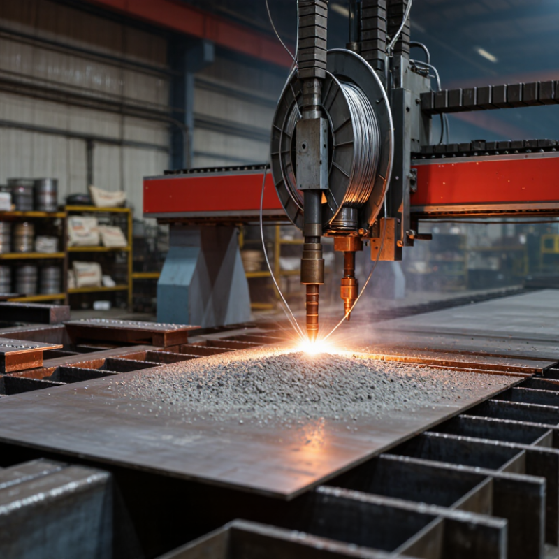
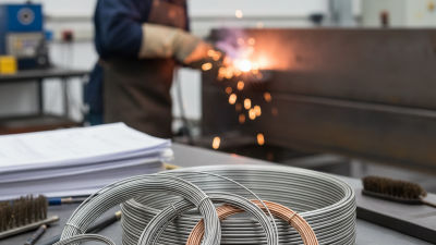
Submerged arc welding (SAW) wire is a continuously fed bare metal electrode used with a separate granular welding flux. |
The wire melts beneath a layer of flux, which shields the arc and molten weld pool from atmospheric contamination. |
Produces a stable, highly protected welding environment. |
The process requires equipment capable of feeding wire and depositing flux accurately. |
| Typical Wire Materials |
Common wire compositions include carbon steel, low-alloy steel, stainless steel, and nickel-based alloys. |
The wire chemistry is selected to provide the required weld-metal strength, toughness, corrosion resistance, or high-temperature performance. |
Suitable wire grades can be matched to a wide range of base metals. |
Wire and flux must be selected as a compatible system; wire chemistry alone does not determine final weld properties. |
| Wire Diameter |
Common diameters are approximately 1.6–6.0 mm, with larger sizes used for high-deposition applications. |
Larger wire generally allows higher welding current and deposition rates, while smaller wire provides better control and access. |
Several diameter options support different plate thicknesses and production requirements. |
Wire diameter must match the power source, contact tip, feed system, joint design, and selected welding parameters. |
| Power Source |
SAW commonly uses constant-voltage or constant-current direct-current systems; alternating current may also be used. |
Direct current supports stable arc starting and directional arc control. Alternating current can help reduce arc blow in certain arrangements. |
Power-source options allow the process to be adapted to single-wire or multi-wire systems. |
Incorrect polarity or power-source settings can affect penetration, bead shape, deposition efficiency, and arc stability. |
| Typical Welding Current |
Many industrial applications operate roughly within 300–1,200 A, although the usable range depends on wire size, polarity, joint design, and equipment. |
Higher current generally increases melting rate and penetration until heat input, distortion, or process limits become controlling factors. |
High current capacity enables rapid welding of thick sections. |
High current can increase heat input, distortion, burn-through risk, and changes in weld-metal properties. |
| Arc Voltage |
A typical operating range is approximately 25–45 V, depending on the welding mode and joint configuration. |
Voltage influences arc length, bead width, penetration profile, and the amount of flux melted. |
Voltage adjustment provides useful control over weld-bead geometry. |
Excessive voltage may cause a wide, shallow bead and increased flux consumption; insufficient voltage may produce a narrow or unstable arc. |
| Travel Speed |
Industrial travel speeds commonly range from about 0.25–2.0 m/min, depending on wire size, current, plate thickness, and the number of wires. |
Travel speed controls heat input per unit length and affects bead size, penetration, and productivity. |
Mechanized travel enables consistent weld quality and repeatable production rates. |
Travel speed must be balanced with current and voltage to prevent lack of fusion, excessive penetration, undercut, or oversized welds. |
| Deposition Rate |
Single-wire SAW can commonly deposit approximately 5–20 kg of weld metal per hour; multi-wire systems can achieve substantially higher rates. |
Continuous wire feeding and concentrated arc energy melt a large quantity of electrode metal efficiently. |
High deposition rate is one of SAW’s main productivity benefits. |
Actual output depends on current, wire diameter, polarity, travel speed, duty cycle, joint access, and flux selection. |
| Flux Function |
Granular flux covers the arc and weld pool and may be fused, bonded, or agglomerated. |
Flux provides shielding, stabilizes the arc, forms slag, refines the weld metal, and can add alloying elements. |
Effective shielding reduces exposure to oxygen and nitrogen and supports clean welds. |
Flux must be kept dry and handled correctly; moisture can contribute to porosity and hydrogen-related cracking risks. |
| Arc Visibility |
The arc is normally hidden beneath the flux layer during welding. |
The granular flux blocks most arc radiation, sparks, and spatter from direct view. |
Lower visible arc glare and very low spatter improve the working environment. |
Operators cannot directly observe the arc and must rely on process settings, instrumentation, and weld-pool or bead indicators. |
| Shielding and Slag |
The melted flux forms a protective slag layer over the solidifying weld metal. |
After cooling, the slag is removed mechanically, usually by chipping, brushing, or specialized equipment. |
Slag protects the weld during solidification and can improve bead appearance. |
Slag removal is an additional operation and may be difficult in narrow grooves or between multiple passes. |
| Deposition Efficiency |
SAW commonly achieves approximately 90–99% electrode deposition efficiency, depending on operating conditions and process setup. |
Very low spatter and continuous wire feeding mean that most of the electrode becomes usable weld metal. |
Less electrode waste than many manual, spatter-producing processes. |
Flux consumption, slag disposal, wire trimming, and unused recoverable flux still affect total material usage. |
| Automation Level |
SAW is normally mechanized or automated, using a welding tractor, gantry, column-and-boom system, or dedicated production line. |
Equipment controls wire feed, travel speed, flux delivery, and often torch alignment. |
Consistent parameters support repeatable weld quality and high production volume. |
It is less practical for irregular, short, highly accessible, or frequently changing welds. |
| Joint Position |
Best suited to flat and horizontal fillet welding positions; some specialized setups support other positions. |
The flux must remain over the arc and weld pool, which is easiest when gravity supports the process. |
Excellent productivity on long, straight, or circumferential welds positioned for stable flux coverage. |
Vertical and overhead welding are generally difficult because flux can spill and the molten pool is harder to control. |
| Suitable Plate Thickness |
Commonly used on medium-to-heavy sections, often from approximately 6 mm upward, with capability extending to much thicker components through multipass welding. |
High heat input and deposition rates allow efficient welding of thick plates and large structural members. |
Well suited to heavy fabrication and deep-groove welds. |
Thin sheet can suffer from burn-through, distortion, or excessive heat input and may be better served by another process. |
| Penetration |
SAW can provide moderate to deep penetration, depending on polarity, current, voltage, wire size, travel speed, and joint preparation. |
Concentrated arc energy melts the base metal and electrode beneath the flux blanket. |
Deep penetration can reduce the number of weld passes in suitable joint designs. |
Excessive penetration or lack of fusion may occur if parameters are not matched to plate thickness and joint geometry. |
| Weld Quality |
Properly controlled SAW can produce smooth, uniform weld beads with low spatter and good mechanical properties. |
Stable mechanized operation, continuous wire feeding, and flux shielding reduce many sources of weld inconsistency. |
High repeatability is valuable for codes, specifications, and production quality control. |
Defects can be difficult to detect during welding because the arc and weld pool are concealed by flux. |
| Main Advantages |
High deposition rate, high productivity, low spatter, good arc shielding, consistent weld appearance, and efficient use of electrode wire. |
Continuous wire feeding and mechanized movement minimize interruptions and reduce operator variability. |
Particularly effective for long, repetitive welds on thick steel components. |
Benefits decrease when welds are short, inaccessible, irregular, or positioned away from flat or horizontal orientations. |
| Main Limitations |
Limited visibility, substantial equipment requirements, flux handling, slag removal, positional restrictions, and sensitivity to surface contamination. |
The process depends on stable workholding, accurate alignment, proper flux coverage, and controlled parameters. |
Strong performance in controlled factory environments. |
Less flexible than manual processes for field repairs, complex geometries, or rapidly changing work locations. |
| Common Applications |
Pressure vessels, storage tanks, structural beams, bridges, ship panels, rail components, wind-tower sections, pipelines, and heavy machinery. |
These products typically contain long seams, circumferential joints, or repetitive fillet welds that can be positioned for mechanized welding. |
High output and repeatability support large-scale fabrication. |
Application suitability depends on material grade, required welding position, access, inspection requirements, and applicable welding procedure. |
| Surface Preparation |
Joint surfaces should be free from excessive rust, oil, paint, moisture, scale, and other contaminants. |
Clean surfaces help maintain arc stability and reduce the risk of porosity, slag inclusions, and lack of fusion. |
Good preparation improves weld consistency and reduces repair work. |
SAW is not a substitute for proper cleaning, fit-up, preheating, or interpass-temperature control. |
| Flux Storage |
Flux should be stored in dry conditions and, when required by the welding procedure, dried or reconditioned before use. |
Moisture control helps limit hydrogen pickup and gas-related weld discontinuities. |
Properly maintained flux supports stable welding and reliable mechanical properties. |
Improperly stored flux may require disposal or controlled redrying, adding time and cost. |
| Post-Weld Operations |
Typical steps include slag removal, visual inspection, dimensional checks, and nondestructive testing where specified. |
Removing slag exposes the weld surface for inspection and preparation for additional passes or coating. |
Mechanized welding simplifies repeatable inspection and production control. |
Slag removal and inspection remain necessary even when the weld appearance is uniform. |