Arc welding is moving from isolated automation projects to connected production systems. According to the International Federation of Robotics (IFR), manufacturers installed 541,302 industrial robots worldwide in 2023. The global operational stock exceeded 4.28 million units. These figures show why robotic welding now matters beyond large automotive plants.
Arc Welding Robot suppliers differ in payload, reach, controller software, torch integration, sensing, and after-sales support. Industry estimates from Grand View Research and Fortune Business Insights indicate continued growth in the industrial robotics and welding automation markets. However, market forecasts vary because analysts use different definitions, regions, and product categories. That uncertainty deserves attention.
This guide examines top arc welding robot manufacturers for global buyers. It focuses on measurable capabilities, not promotional rankings alone. Key factors include arc stability, seam tracking, offline programming, safety functions, spare-parts access, and local technical service. Buyers should also compare total ownership costs, including fixtures, integration, training, maintenance, and energy use.
The best system is not always the fastest robot. A compact cell may outperform a larger system when factory space, changeover time, or operator skill is limited. Real production samples matter. So do documented cycle times.
Some manufacturers publish impressive specifications but provide limited application data. That gap can complicate purchasing decisions. Therefore, this overview combines manufacturer information with recognized industry research, including IFR robotics data and market studies from established research firms. Results still depend on material thickness, joint design, welding process, and plant conditions. A careful buyer should validate every claim through trials, references, and regional service checks.
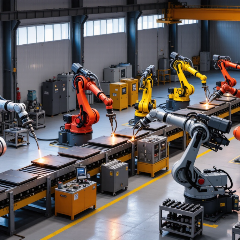
A six-axis arc welding robot uses six coordinated joints to position the torch around complex workpieces. This flexibility helps maintain a stable torch angle near corners, flanges, and curved seams. Payloads commonly range from 6 to 20 kg. However, payload does not mean welding power. It includes the torch, cables, dress pack, sensors, and mounting hardware. A 6 kg arm may suit a compact MIG setup, while a 20 kg model offers more allowance for heavier equipment.
Real factory evaluation should start with the weld cell, not the robot catalogue. Measure part weight, fixture reach, cable movement, and access to every seam. A robot may reach the workpiece but still fail to hold the correct travel angle. That detail is easy to miss. Cycle-time claims also need practical testing with loading, repositioning, wire changes, and inspection included. Small gaps between simulation and production can become expensive.
Tips: Leave payload headroom, preferably 15–25 percent. Check wrist clearance before approval. Test the longest cable route. Ask for application samples using similar steel thickness and joint design. Do not judge a system by arm speed alone; arc stability, programming tools, maintenance access, and operator training matter equally. A lower-cost cell may look attractive, yet limited service support can weaken reliability over several years. Careful buyers should document these trade-offs before selecting a global supplier.
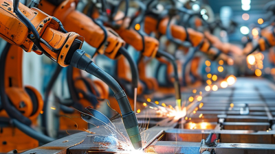
Global buyers often compare five leading arc-welding robot manufacturers by more than catalog price. Their real differences appear in reach, controller design, software, service coverage, and welding stability. One supplier may offer excellent motion accuracy, while another provides stronger process libraries or simpler operator training.
In factory trials, I check bead consistency after several hours, not after one perfect sample. A six-axis arm with a 1.8-meter reach may suit vehicle frames, but it can waste floor space on smaller assemblies. Payload also matters. Heavy torches, wire feeders, and sensor packages can reduce acceleration. Small details matter.
Service access can decide the purchase. Ask how quickly technicians reach your plant, how spare parts are stocked, and whether remote diagnostics work during production. European and Asian suppliers often differ in local support structure, integration partners, and documentation style. Some platforms provide polished digital tools, yet their setup may feel complex for a small workshop. Others are easier to learn but offer fewer advanced monitoring functions.
The comparison is not perfectly tidy. I have seen buyers select the cheapest cell, then spend more on integration changes. A practical test should include corner joints, changing plate thickness, and torch maintenance. Request measured cycle times, sample welds, operator training plans, and references from similar factories. Marketing claims help, but production evidence carries more weight.
When comparing arc welding robot manufacturers, buyers should examine repeatability under real production conditions. A specification of ±0.02–0.08 mm sounds precise, but its value depends on calibration, torch condition, and fixture stability. A robot may repeat a programmed path accurately while the workpiece shifts slightly. That difference can affect bead placement, especially on thin steel parts.
Test data matters.
For welding operations using 100–500 A, the robot must manage heat, cable weight, and torch movement without hesitation. Lower current settings suit smaller joints and thinner materials. Higher current levels support deeper penetration, but they also increase spatter, distortion, and thermal stress. Cooling capacity, wire-feeding consistency, and power-source communication should be checked together. Do not judge the robot arm alone.
A reliable evaluation includes sample welds, dimensional checks, and several production cycles. Measure the same joint after warm-up, not only during a short demonstration. Record arc starts, stops, weaving accuracy, and recovery after interruptions. ±0.02 mm repeatability may be achievable in controlled conditions, while ±0.08 mm may be more realistic on a larger cell with flexible tooling. That gap deserves discussion. A polished datasheet cannot reveal every factory problem. Ask for test conditions, maintenance intervals, and evidence from comparable materials before selecting equipment.
Top Arc Welding Robot Manufacturers for Global Buyers
When comparing arc welding robot manufacturers, inspect automation depth, not brochure speed. Seam tracking uses laser or through-arc sensing to correct joint variation during welding. This matters when plate edges shift, gaps widen, or fixtures lose repeatability. Positioners rotate the workpiece, keeping the weld pool near its preferred angle. Operators spend less time repositioning heavy assemblies.
The International Federation of Robotics reported 541,302 industrial robot installations worldwide in 2023. Its World Robotics 2024 report also recorded global robot density at 162 units per 10,000 manufacturing employees. These figures show strong automation demand, but welding performance still depends on integration quality. Deloitte’s 2023 Smart Manufacturing and Operations Survey linked smart manufacturing programs with measurable production and productivity improvements. In welding case studies, seam tracking and coordinated positioners commonly support gains of 10–30%, depending on part mix and baseline efficiency.
The number is not guaranteed. Poor torch access can erase it. Buyers should request cycle-time records, arc-on percentage, tracking accuracy, and sample welds using their own material. Ask whether the controller logs wire consumption, fault codes, and rework causes. A useful trial includes awkward corners, changing joint gaps, and realistic fixture loading. That exposes weaknesses quickly. A fast robot with weak sensing may create more inspection work, not less.
The following table summarizes commonly specified capabilities and benchmark ranges for industrial arc-welding robot systems. Values are application-dependent and are not assigned to any specific company or brand.
| Evaluation Dimension | Typical Industrial Specification | Automation Feature | Buyer Benefit | Key Verification Point |
|---|---|---|---|---|
| Robot Payload | Approximately 6–20 kg | Supports a welding torch, cable package, torch-cleaning equipment, and selected sensors. | Provides sufficient capacity for standard MIG/MAG and flux-cored arc-welding tools without overloading the robot wrist. | Confirm the complete tool package weight, center of gravity, wrist moment, and allowable inertia. |
| Working Reach | Approximately 1.4–2.0 m | Six-axis articulated motion with optional external axes. | Reduces repositioning and helps cover long weld seams or multiple work areas. | Check reach at the required welding angle, not only the robot's maximum theoretical reach. |
| Positioning Accuracy | Typical repeatability: about ±0.02–0.10 mm | High-repeatability programmed motion and path interpolation. | Improves consistency between production cycles and supports repeatable weld placement. | Request the applicable repeatability standard, test conditions, and payload assumptions. |
| Seam Tracking | Contact, through-arc, laser, or vision-based systems | Detects joint deviation caused by part tolerance, thermal distortion, or fixture variation. | Reduces manual touch-up and helps maintain torch position along changing weld paths. | Compare sensor type, tracking speed, detection range, minimum joint size, and calibration method. |
| Through-Arc Tracking | Best suited to compatible continuous arc-welding processes | Uses arc signal changes during controlled weaving to correct torch position. | Offers a practical solution where laser sensing is unnecessary or difficult to install. | Verify compatibility with welding current, voltage, weave pattern, material, and joint geometry. |
| Laser Seam Tracking | Non-contact profile measurement before or during welding | Scans joint position and profile without relying solely on the welding arc. | Supports pre-weld correction and can improve performance on variable gaps and complex joints. | Check optical access, surface reflectivity, fume protection, resolution, and sensor mounting space. |
| Positioner Integration | Single-axis to multi-axis synchronized positioners | Rotates or tilts the workpiece while the robot maintains the programmed torch path. | Improves welding position, reduces robot reach limitations, and can increase arc-on time. | Confirm rated payload, allowable eccentric load, rotation speed, indexing accuracy, and synchronization method. |
| Positioner Payload | Common configurations: approximately 250–2,000 kg | Handles small fabricated parts through larger welded assemblies. | Enables flexible cell design for different component sizes and production volumes. | Include fixture weight, workpiece offset, center of gravity, and dynamic load in the calculation. |
| Welding Process Compatibility | MIG/MAG, flux-cored arc welding, and selected TIG applications | Interfaces with digital welding power sources, wire feeders, gas systems, and process monitoring. | Allows the same robotic platform to support multiple materials, joint types, and wire diameters. | Validate communication protocol, process package, wire size, welding current range, and parameter control. |
| Torch Management | Automatic cleaning, wire cutting, anti-spatter application, and calibration | Performs routine torch-maintenance tasks within the cell. | Reduces unplanned stops and helps maintain consistent wire stick-out and torch geometry. | Review consumable replacement intervals, maintenance access, spare-parts availability, and safety interlocks. |
| Cell Safety | Fencing, interlocked gates, emergency stops, and safety-rated monitoring | Integrates robot, positioner, welding equipment, and access protection into one safety circuit. | Supports safer operation and helps meet applicable workplace and machine-safety requirements. | Confirm conformity requirements for the destination market and responsibility for final system validation. |
| Typical Productivity Opportunity | Approximately 10–30% in suitable applications | Combines robotic motion, synchronized positioning, seam tracking, and reduced manual handling. | May increase arc-on time, improve repeatability, and reduce rework compared with manual welding. | Require a baseline comparison using cycle time, arc-on time, operator hours, rework rate, and utilization. |
| Programming and Changeover | Offline programming, touch-up teaching, templates, and parameter libraries | Stores proven weld schedules and simplifies repeat production of similar parts. | Shortens changeover time and reduces dependence on repeated manual programming. | Evaluate training requirements, offline-programming workflow, simulation accuracy, and file compatibility. |
| Service and Global Support | Commissioning, remote diagnostics, operator training, and local spare-parts access | Provides technical support throughout installation and production ramp-up. | Reduces downtime risk for international buyers and improves long-term system availability. | Compare response times, service coverage, language support, warranty terms, and technician availability. |
Note: Productivity gains of 10–30% are benchmark-style planning ranges rather than guaranteed results. Actual performance depends on part mix, fixture quality, weld length, operator workflow, robot utilization, material, joint consistency, and the level of system integration.
Global buyers should evaluate welding robot manufacturers through documented safety compliance, not catalog claims. ISO 10218 covers robot and system safety, including safeguarding, stopping functions, and integration procedures. Request the latest conformity documents, risk assessments, validation records, and operating manuals. A certificate alone is not enough.
ISO 13849 focuses on safety-related control systems. Ask whether emergency stops, gate interlocks, light curtains, and enabling devices achieve the required Performance Level. The supplier should explain the safety circuit design and validation method. During a factory review, inspect cabinet labels, guarded access points, and restart behavior after power loss. Small details matter.
CE marking requires the manufacturer to complete applicable conformity procedures for the machinery placed on the European market. Check the Declaration of Conformity and technical file references. For North American projects, clarify UL certification, recognized components, panel construction, and site inspection responsibilities. Requirements can vary by application and location.
Do not rely on copied templates.
A capable supplier should provide traceable test records, trained commissioning personnel, and clear maintenance instructions. Ask for weld-cell drawings showing robot reach, fixture access, cable routing, and fume extraction interfaces. Some assessments overlook manual loading tasks. That weakness can appear after installation. Independent review before shipment may reveal gaps, although it adds time and cost.