- HOME
- ABOUT US
- PRODUCTS
- TECHNOLOGY R&D
- PROJECTS
- NEWS
- Blog
- CONTACT US
inquiry
Leave Your Message
Choosing the best Arc Welding Robot is not simply a matter of comparing payloads, prices, or brand names. The decision affects weld consistency, operator safety, production speed, maintenance costs, and long-term flexibility. A robot that performs well on a large automotive line may struggle with short runs, changing joint designs, or limited floor space.
Industry data shows why this choice deserves careful evaluation. The International Federation of Robotics reported 541,302 industrial robots installed worldwide in 2023, confirming strong demand for automated manufacturing. The American Welding Society has also projected a shortage of approximately 330,000 welding professionals in the United States by 2028. Automation can help, but it cannot replace sound process planning. Poor fixturing still creates poor welds.
A reliable selection process should examine welding current, reach, repeatability, torch access, positioners, seam tracking, programming methods, and after-sales support. Consider the workpiece on the shop floor. Is it oily, oversized, reflective, or frequently redesigned? These details matter more than a polished brochure. Independent studies from organizations such as IFR, AWS, and ISO emphasize measurable performance, operator competence, and process control. However, published figures vary by region and application, so they should guide decisions rather than dictate them.
This guide explains how to compare robot specifications with real production demands. It also addresses integration, safety, training, and total cost of ownership. The “best” system may not be the fastest one. It may be the simplest system that delivers stable welds every shift. Some uncertainty will remain, and that is worth acknowledging before signing a purchase order.
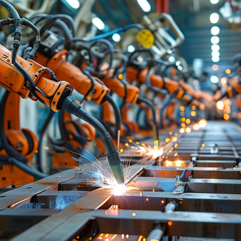
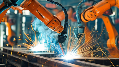
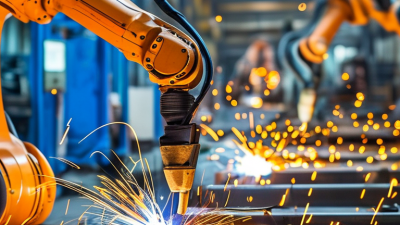
Choosing the best arc welding robot starts with understanding what it actually does. An arc welding robot combines a programmable arm, welding power source, wire feeder, torch, and control system. Each part affects weld quality and production stability.
The controller guides the torch along a programmed path. The power source manages current, voltage, and arc behavior. The wire feeder supplies filler metal at a controlled speed. Shielding gas protects the molten weld pool from contamination. Sensors can detect joint position, torch distance, or changes in the workpiece. These functions help maintain consistent bead shape, penetration, and travel speed.
Small details matter.
In a practical welding cell, the robot must reach every joint without awkward wrist movement. Payload capacity should include the torch, cables, and any tooling. A positioner can rotate the workpiece, keeping the weld in a more favorable position. Seam tracking may correct small deviations, but it cannot repair poor joint preparation. That is often overlooked.
Safety systems also deserve careful attention. Interlocks, guarding, emergency stops, and controlled access protect operators during automatic movement. Good software should make parameter changes traceable and training manageable. A perfect simulation is not a finished weld. Real parts may vary, fixtures may loosen, and heat can cause distortion. Trial welds, visual inspection, and suitable testing remain necessary. The best choice is not always the fastest robot; it is the system that delivers repeatable welds under real factory conditions.
A practical comparison of robot configuration, welding capability, integration requirements, and selection criteria
| Evaluation Dimension | Typical Data or Range | Core Function or Meaning | Why It Matters in Selection | Recommended Verification |
|---|---|---|---|---|
| Robot Axes | Usually 6 axes for the robot arm; external positioners commonly add 1–2 controlled axes | Provides movement in position, orientation, and torch angle | More coordinated axes can improve access to complex joints and reduce awkward torch angles | Check the required welding orientations, fixture access, and coordinated-motion capability |
| Horizontal Reach | Approximately 1.4–3.0 m for many industrial arc-welding configurations | Defines how far the torch can reach from the robot base | The reach must cover the complete work envelope without excessive joint extension | Create a cell layout using the actual part dimensions, fixture locations, and torch clearance |
| Rated Payload | Common arc-welding robot classes are about 4–20 kg; payload includes torch, cables, sensors, and tooling | Specifies the mass the wrist can carry while maintaining rated performance | Insufficient payload can cause vibration, reduced accuracy, cable stress, or overload alarms | Calculate total tool mass and center of gravity; leave a practical safety margin |
| Repeatability | Many industrial robots specify repeatability in the range of approximately ±0.02–0.08 mm | Describes how closely the robot returns to a programmed position | Consistent torch positioning supports stable arc starting, bead placement, and repeatable quality | Confirm the stated value under the applicable test standard and operating conditions |
| Welding Processes | MIG/MAG and FCAW are widely used; TIG and pulsed processes require compatible equipment and control | Controls the arc, wire feed, shielding gas, travel motion, and weld parameters | The process must match material, thickness, joint design, production rate, and required finish | Run sample welds using production materials, consumables, joint types, and approved procedures |
| Torch Angle and Travel Control | Programmed travel speed, work angle, travel angle, contact-tip-to-work distance, and weaving pattern | Maintains consistent torch geometry and motion along the weld path | Improves penetration consistency, bead appearance, and repeatability | Check whether the controller supports required weave patterns, speed limits, and process parameters |
| Seam Tracking | Contact and through-arc tracking are common; laser tracking is used when higher geometric measurement capability is needed | Detects joint deviation and adjusts the torch path during welding | Useful for variable part fit-up, distortion, long seams, and inconsistent fixturing | Evaluate tracking accuracy on actual joint gaps, surface conditions, and weld speeds |
| Touch Sensing | Uses electrical contact between the electrode or torch and the workpiece before welding | Finds the physical location of the joint or part reference | Compensates for fixture and part-position variation before arc ignition | Confirm compatibility with the welding process, torch design, and workpiece surface |
| Wire-Feeder Integration | Integrated control of wire speed, arc voltage or trim, welding current, and gas-related signals | Synchronizes wire delivery and power-source settings with robot motion | Stable wire delivery helps reduce spatter, burnback, feeding faults, and inconsistent welds | Verify communication protocol, wire diameter range, liner routing, and service accessibility |
| Workpiece Positioner | One- or two-axis positioners are commonly used to rotate, tilt, or index the workpiece | Places the joint in a more favorable welding position | Can reduce robot reach requirements, improve weld access, and support higher deposition efficiency | Check load capacity, workpiece inertia, rotation range, indexing accuracy, and coordinated control |
| Welding Duty Cycle | Power-source duty-cycle ratings are commonly expressed at a specified current and ambient condition, often over a 10-minute test period | Indicates how long welding can continue before thermal limits are reached | A suitable rating prevents overheating during long welds and high-production operation | Compare duty-cycle data at the actual welding current, voltage, ambient temperature, and duty pattern |
| Cell Safety | Typical safeguards include perimeter guarding, interlocked gates, emergency stops, and presence detection | Prevents personnel from entering hazardous motion, arc-flash, heat, and fume areas | Safety design is essential for regulatory compliance and reliable production operation | Complete a documented risk assessment covering robot motion, welding arc, fumes, fixtures, and maintenance |
| Programming and Offline Simulation | Common functions include teach pendant programming, path editing, weld schedules, job management, and offline simulation | Creates, tests, stores, and adjusts robot welding programs | Better programming tools can reduce commissioning time and production changeover time | Test program creation, revision control, collision checking, and operator usability with the production team |
| Maintenance and Consumables | Regular tasks include contact-tip, nozzle, liner, torch, cable, wire-feed, and calibration inspection | Maintains arc stability, torch accuracy, wire delivery, and equipment availability | Accessible service points and standard consumables reduce downtime and maintenance cost | Review preventive-maintenance intervals, spare-part availability, calibration procedures, and technician training |