7 Best Arc Welding Robots for Manufacturers in 2026
Arc welding is no longer just a way to increase output. For manufacturers, it can help manage repeatable welds, changing product mixes, and hard-to-fill shop-floor roles. The scale of industrial automation is growing: the International Federation of Robotics reported 541,302 industrial robots installed worldwide in 2023, with 4.28 million operating globally. These figures cover many industries and applications, not welding alone, but they show the expanding automation landscape.
Workforce pressure adds urgency. A 2024 Deloitte and Manufacturing Institute study estimated that U.S. manufacturers may need 3.8 million additional employees by 2033, with up to 1.9 million roles potentially unfilled. An Arc Welding Robot can support production, but it is not a shortcut around process control. Poor joint fit-up, unstable fixtures, or inconsistent wire feed can still produce defects—only faster.
This guide compares seven arc welding robots for manufacturers in 2026, focusing on practical selection factors: reach, payload, torch access, path accuracy, programming effort, and integration support. A compact cell may suit short, repeatable seams; larger fabrications may need extended reach and positioner coordination. The right choice depends on the part, process, and people maintaining the system. Specifications matter. So does the demo. Even a strong robot can disappoint when real-world parts differ from sample pieces.
What Arc Welding Robots Are and How They Work
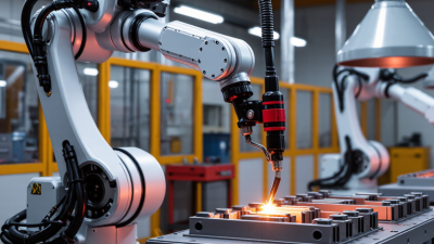
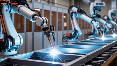
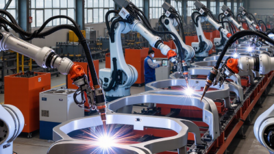
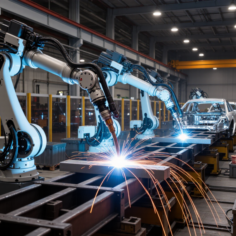
Arc welding robots are programmable machines that guide a welding torch along a planned joint. A typical system includes a robotic arm, welding power source, wire feeder, torch, and safety enclosure. The power source supplies the electrical energy that creates the arc, while the feeder delivers wire at a controlled rate. Shielding gas helps protect the molten weld pool from contamination.
The controller coordinates torch movement with settings such as travel speed, voltage, and wire-feed speed. An operator programs the weld path and positions the parts in a fixture; some cells also use sensors to locate joints or adjust for small variations. Fit-up matters. A gap or misaligned edge can still produce a poor weld, even when the robot repeats its motion precisely. Before production, technicians typically check the torch angle, workpiece position, and sample welds. Automation helps with repeatability, but it does not remove the need for skilled setup and inspection. The tricky part is often the workpiece, not the robot. Real parts can vary more than the program expects.
7 Best Arc Welding Robots for Manufacturers in 2026 - What Arc Welding Robots Are and How They Work
| Robot setup |
Typical reach |
Typical arm payload |
Common arc process |
Best suited for |
Key consideration |
| Compact 6-axis cell |
About 1.4–1.6 m |
About 5–10 kg |
MIG/MAG; TIG in suitable applications |
Small parts, brackets, and compact workstations |
Check torch, cable, and dress-pack clearance at every joint position. |
| General-purpose 6-axis cell |
About 1.7–2.0 m |
About 8–16 kg |
MIG/MAG; TIG where process requirements allow |
Mixed-size fabrications and everyday production welding |
A common flexible format, but fixture access and cycle time still need validation. |
| Long-reach 6-axis cell |
About 2.0–3.0 m |
About 6–16 kg |
Primarily MIG/MAG |
Large frames, long seams, or reaching across a fixture |
Longer reach does not guarantee access to every weld; assess stiffness and torch angle. |
| High-payload 6-axis cell |
About 1.8–2.7 m |
About 20–50 kg or more |
MIG/MAG; process depends on tooling and application |
Heavy torches, auxiliary equipment, or larger end-of-arm tooling |
Payload must include the torch, cables, sensors, and any mounted equipment. |
| Robot with a positioner |
Typically about 1.4–2.0 m robot reach |
Robot commonly about 5–16 kg; positioner rated separately |
MIG/MAG; TIG for compatible parts and production needs |
Parts needing multiple weld faces or more consistent welding orientation |
Coordinate robot and positioner motion, guarding, and workholding as one cell. |
| Track-mounted robot |
Robot reach plus linear travel; track length is application-specific |
Robot commonly about 5–20 kg; track load rated separately |
Primarily MIG/MAG |
Long weldments or multiple stations served by one robot |
Track alignment, cable management, and coordinated travel affect accuracy and uptime. |
| Collaborative arc-welding setup |
Often about 1.0–1.3 m |
Often about 5–12 kg |
Usually MIG/MAG with an application-specific package |
Short-run work and tasks where simpler programming or redeployment is valuable |
Collaborative rating alone does not make arc welding safe for people nearby; a risk assessment and appropriate guarding are essential. |
Note: These are broad, indicative configuration ranges, not specifications for a particular robot. Actual reach, payload, accuracy, process capability, and safety requirements vary by model and application.
How to Evaluate Arc Welding Robots for Manufacturing
Evaluating an arc welding robot starts with the joint, not the headline speed. The International Federation of Robotics reported 541,302 industrial robots installed worldwide in 2023, with 4,281,585 operating in factories. That scale signals broad adoption, but it does not prove a robot suits your weld cell. Fit matters. Map part variation, torch access, weld length, and changeover frequency. Then compare candidate systems using the same representative parts, wire, and production settings.
Ask for measured results. Track arc-on time, cycle time, rework, and uptime across repeated runs—not just a polished demonstration. A stable bead on a flat coupon may not predict performance on a fixture with tight access. IFR’s World Robotics 2024 report also shows how widely industrial robots are deployed; your own process data must determine whether automation will pay off. It is easy to overlook programming and fixture adjustments. Those hours count.
Check integration before purchase. Confirm compatibility with existing power sources, positioners, extraction, and shop-floor controls. Review guarding and risk assessment against applicable machinery-safety requirements, and ask who handles maintenance and operator training. Compare total cost over the expected service life, including consumables, downtime, and support. A small trial helps expose gaps, though it may not capture every shift or part variation. Keep the test conditions documented.
Seven Leading Arc Welding Robots for Manufacturers in 2026
Manufacturers comparing seven leading arc-welding robot configurations should start with the joint, not the brochure. A compact six-axis robot fits short-reach workcells and small components. High-payload models handle larger torches or heavier tooling. Collaborative systems can suit lower-volume work, but still need a carefully assessed safety setup. Fit matters most.
For long weld seams, rail-mounted robots extend the working envelope. Overhead-mounted systems can free valuable floor space. Dual-station cells let operators load one fixture while the robot welds another. Vision-guided systems help locate parts when positioning varies. Each option has trade-offs: a longer reach may add setup complexity, while added sensing needs calibration and maintenance.
The International Federation of Robotics’ World Robotics 2024 report recorded 541,302 industrial robot installations worldwide in 2023, up 10% from 2022. That figure covers industrial robots broadly, not arc-welding systems alone, so it signals automation demand rather than welding-specific growth. Compare the seven configurations using bead quality, duty cycle, reach, fixture access, and changeover time. Ask for sample welds on your actual material and joint. One caveat: a strong demonstration may not reflect months of production, and I would not choose from cycle time alone.
Comparing Robot Performance, Capabilities, and Applications
Arc welding robot performance depends on more than travel speed. Compare reach, payload, repeatability, torch access, and the robot’s ability to maintain a steady arc along the joint. In a tight fixture, a compact arm may outperform a faster model simply because it can reach the weld without repositioning the part. Small details matter.
The International Federation of Robotics reported 541,302 industrial robot installations worldwide in 2023, with 4,281,585 units operating by year-end (World Robotics 2024). Those figures cover all industrial robot applications, not welding alone, but they show why manufacturers increasingly assess automation for repeatable production. For arc welding, also examine seam tracking, offline programming, and compatibility with the welding power source. A high payload rating does not guarantee useful torch access.
Applications vary. High-volume automotive cells may favor fast cycle times and coordinated positioners, while short-run fabrication often needs quick reprogramming and flexible fixtures. Compare each candidate using the same joint, material thickness, and weld procedure; otherwise, performance claims can mislead. Check duty-cycle limits and cable routing during a real production trial. Rankings are imperfect. A system that excels on long, straight seams may struggle with awkward joints, and that trade-off is easy to overlook.
7 Best Arc Welding Robots for Manufacturers in 2026
Typical deposition-rate ranges for common arc-welding processes help manufacturers match robotic systems to production needs.
How to read: Bars show the midpoint of each indicative industry range; the range is available on hover. Actual deposition rates vary with material, wire or electrode, joint design, position, and parameters. This is a process-level capability comparison, not a model-specific robot test or ranking.
Integrating and Maintaining Arc Welding Robots in Production
Integrating and Maintaining Arc Welding Robots in Production
An arc welding robot performs best when the whole cell is planned around the weld, not just the arm. Check part variation, fixture access, torch clearance, and cable routing before installation. A small fixture shift can move the seam outside the programmed path. Confirm that the power source, extraction system, guarding, and robot controls work together. Then test real parts, including awkward joints and production tolerances. A neat demonstration weld is not enough.
Tips: Keep a few sample parts for repeatable checks. Mark fixture positions clearly. Record approved weld settings and program revisions. Small gaps matter.
Maintenance should follow operating conditions, not a calendar alone. Inspect the contact tip, nozzle, torch liner, and cables for wear or spatter buildup. Clean fixtures before residue changes how parts sit. Monitor alarms and weld results for patterns; a gradual rise in rework may point to worn consumables or inconsistent fit-up. Keep maintenance records brief but useful, with dates, parts changed, and observed symptoms. It is tempting to automate every variation, but that can hide poor part presentation. Review the process with operators and weld technicians after changes. A little uncertainty remains: new materials or shifted tolerances may require fresh trials, even when the old program still runs.